Additional Software
Discover our specialized Software Defined Radio tools for advanced signal analysis and processing
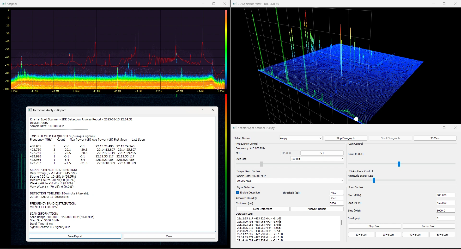
Khanfar Spot Scanner
Advanced Multi-SDR Spectrum Analyzer with Intelligent Signal Detection
Khanfar Spot Scanner is a powerful and feature-rich spectrum analyzer designed for radio frequency enthusiasts, wireless security researchers, and professional RF engineers. Supporting multiple SDR hardware devices including RTL-SDR, Airspy, and HackRF, this software provides comprehensive spectrum visualization, automated signal detection, and in-depth analysis reporting.
Key Features
Multi-SDR Device Support
- RTL-SDR (24MHz-1766MHz frequency range)
- Airspy (24MHz-1800MHz frequency range)
- HackRF (1MHz-6GHz frequency range)
- Automatic hardware detection and configuration
Advanced Signal Detection & Analysis
The heart of Khanfar Spot Scanner is its intelligent signal detection system that can identify RF signals across wide frequency bands with remarkable precision:
- Threshold-Based Detection: Configure sensitivity based on your environment
- Edge-Aware Detection: Special algorithms to accurately detect signals at spectrum boundaries
- Frequency Refinement: Advanced algorithms that improve frequency precision during scanning
- Detection Logging: Comprehensive timestamped logs of all detected signals
Comprehensive Analysis Reports
Generate detailed statistical reports about your RF environment:
- Signal Distribution Analysis: Understand the frequency band allocation of detected signals
- Signal Strength Classification: Categorization of signals from very weak to very strong
- Detection Timeline: Temporal analysis of when signals were detected
- Top Frequencies Report: Identification of the most active frequencies
- Export Capabilities: Save reports for further analysis or documentation
Visualization Options
- Fosphor Acceleration: GPU-accelerated spectrum display
- Waterfall Display: Time-domain visualization of spectrum activity
- 3D Visualization: Immersive three-dimensional representation of the RF spectrum
Getting Started
Important Requirements:
- Connect your SDR hardware before launching the application
- To use signal detection features, you must first:
- Start the flowgraph (click "Start Flowgraph")
- Launch the 3D View (click "3D View")
- Enable Detection (check "Enable Detection" in Signal Detection panel)
Setting Up Signal Detection
Detection Parameters:
- Threshold (dB): The relative power level above the noise floor required to trigger detection. Lower values increase sensitivity but may produce false positives. Recommended starting value: -40dB
- Absolute Min (dB): The minimum absolute power level required for detection, regardless of the relative threshold. Helps filter out weak signals. Recommended starting value: -15dB
- Cooldown (ms): Minimum time between detections to prevent duplicate logging of the same signal. Recommended: 2000ms for general use
Recommended Scanning Settings:
- RTL-SDR: Use 500ms dwell time for best detection performance while scanning
- Airspy and HackRF: We recommend dwell time for best detection performance 50ms and up.
Optimizing 3D Visualization
The 3D view provides an immersive visualization of the spectrum and is required for signal detection:
- Use the 3D Amplitude Scale control to adjust the height of signals in the visualization
- Higher amplitude scales make weaker signals more visible
- Recommended starting value: 5.0x (adjust based on your signal environment)
Hardware Considerations
- For best results, use a high-quality antenna appropriate for your frequency range of interest
- Use a USB 3.0 port for Airspy and HackRF devices to ensure adequate bandwidth
- RTL-SDR devices work well with USB 2.0 ports
System Requirements
- RAM: 16GB minimum
- CPU: Intel i5 9.5th generation or equivalent
- GPU: NVIDIA GTX 1650 4GB or equivalent minimum
Unzip Password: 1234
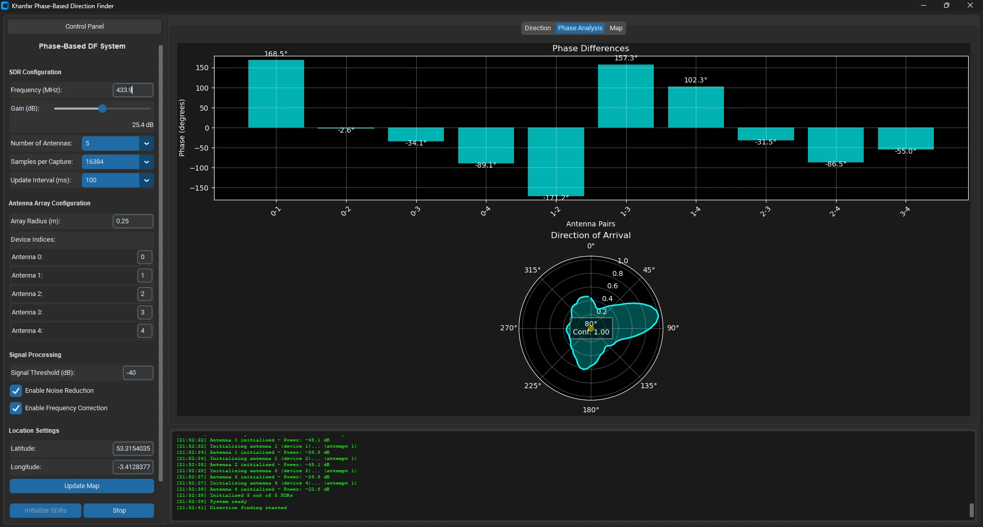
Khanfar Phase-Based Direction Finding
Advanced Multi-SDR Direction Finding System Using Phase Difference Analysis
Khanfar Phase-Based DF is advanced direction finding software that uses phase difference analysis to determine the bearing of radio signal sources. Unlike traditional direction finding systems that rely on directional antennas and signal strength comparison, this software utilizes an array of omnidirectional antennas and sophisticated signal processing algorithms to analyze the phase relationships between received signals.
Key Features
Direction Finding Capabilities
- Real-time direction visualization on compass and map displays
- Multiple antenna array support (3-8 antennas in circular configuration)
- Phase difference analysis for accurate bearing determination
- Confidence metrics for reliability assessment
- Direction finding accuracy: Typically ±5° under ideal conditions
Theory of Operation
- Phase-Based Principle: Analyzes phase differences between signals arriving at different antennas
- Correlation Analysis: Compares measured phase differences with theoretical patterns
- Mathematical Processing: Advanced algorithms for optimal direction determination
- Confidence Calculation: Evaluates strength and uniqueness of correlation peaks
Hardware Compatibility
- Multiple RTL-SDR Receivers (3-8 units)
- Omnidirectional antenna arrays in circular configuration
- Frequency range: 24 MHz to 1.7 GHz (limited by RTL-SDR hardware)
- Minimum signal level: Typically -60 to -80 dBm (gain dependent)
- Update rate: 1-10 updates per second (setting dependent)
Advanced Signal Processing
- Noise Reduction: Adaptive algorithms to separate signal from noise
- Frequency Correction: Compensates for frequency differences between SDR receivers
- Customizable Parameters: Adjust threshold, samples, and processing for your environment
- Signal Threshold Control: Configure sensitivity based on your environment
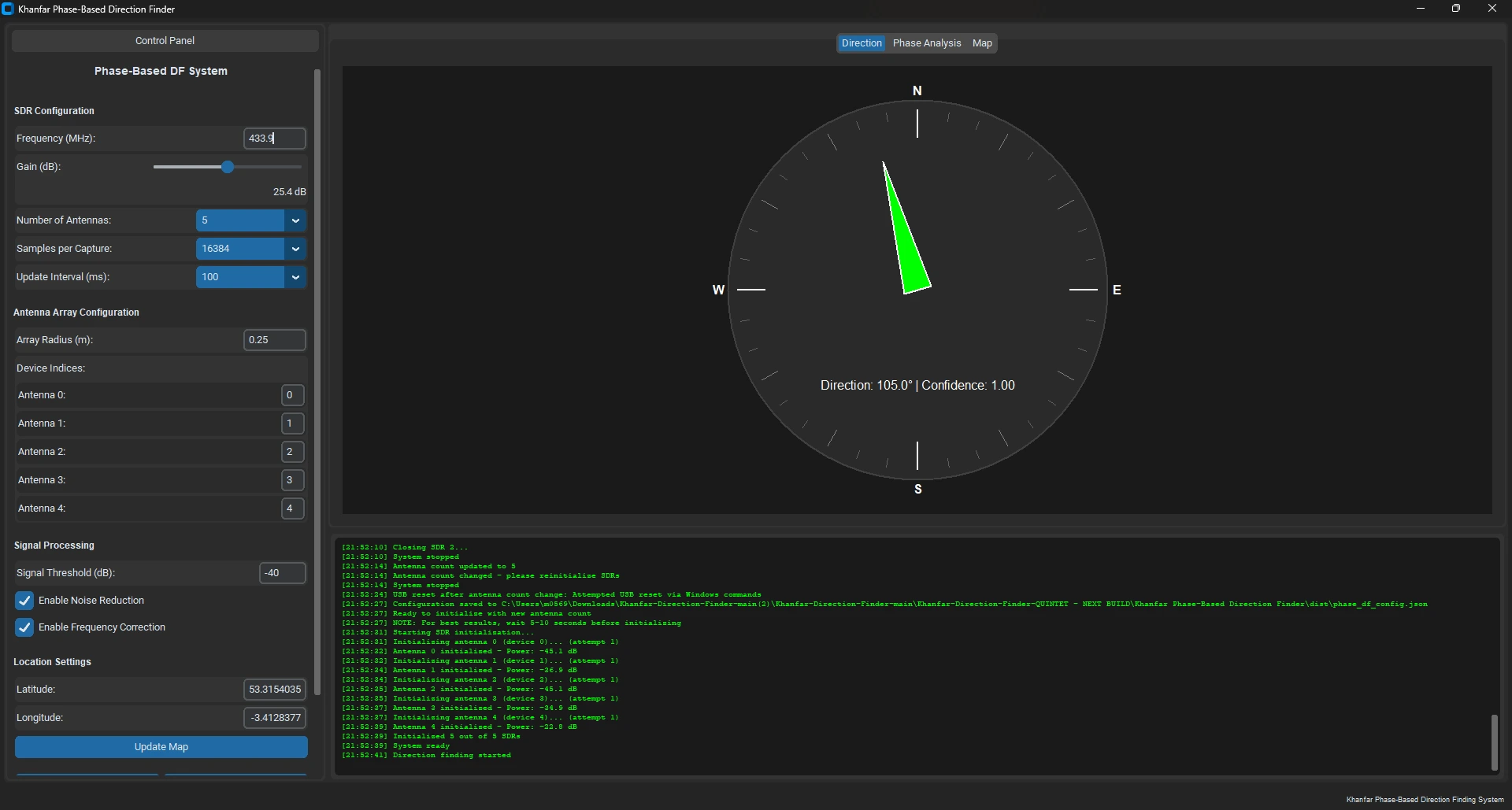
Visualization & Analysis Tools
- Compass Display: Intuitive visualization with confidence indication
- Phase Differences Plot: Shows measured phase differences between antenna pairs
- Direction of Arrival Plot: Polar plot showing correlation between measured and theoretical phase patterns
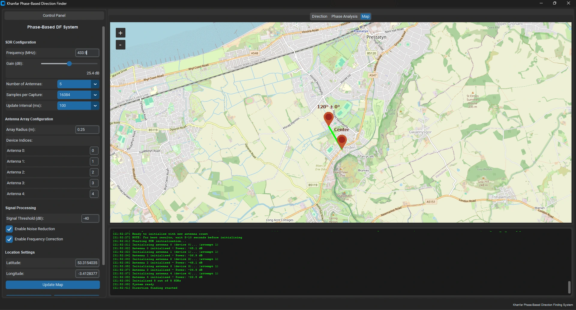
- Map Integration: Geographical visualization with location coordinates input
Technical Note: RTL-SDR Phase Synchronization
Addressing Phase Coherence in Multi-SDR Direction Finding
Standard RTL-SDR dongles present inherent challenges when used for phase-based direction finding due to their independent oscillators, sample timing offsets between ADCs, and phase differences between tuners. These devices were not originally designed for coherent phase applications.
Our Dynamic Calibration Approach
Rather than requiring hardware modifications for perfect synchronization, the Khanfar Phase-Based DF system employs a continuous software-based correction approach:
- Reference Selection: One SDR is designated as the reference for each processing cycle
- Cross-Correlation Analysis: The system computes cross-correlation between each SDR's samples and the reference samples
- Phase Offset Extraction: The algorithm identifies the maximum correlation point and extracts the phase offset
- Complex Phase Correction: A mathematical correction is applied by multiplying samples by exp(-j * phase_offset)
Key Advantages
This approach works effectively because:
- Continuous Recalibration: The correction is applied constantly during operation, not just once at startup
- Relative vs. Absolute: For direction finding applications, relative phase relationships are more important than absolute synchronization
- Drift Compensation: The technique mitigates oscillator drift issues that would accumulate over time
- Frequency Tolerance: Cross-correlation can compensate for moderate frequency differences between dongles
Practical Considerations
While this method enables phase-based direction finding with standard RTL-SDRs, it's important to note:
- Performance is best with moderately strong, continuous signals
- The system cannot completely eliminate sample timing differences without hardware modifications
- For ultimate precision, synchronized clock hardware would yield superior results
Our approach makes standard RTL-SDRs viable for phase-based direction finding without requiring hardware modifications, opening this technology to a wider range of applications and users.
System Setup
Hardware Requirements:
- Multiple RTL-SDR receivers (3-8 units) with stable oscillators (TCXO preferred)
- Omnidirectional antennas - simple vertical dipoles tuned to your frequency of interest
- Circular mounting array - non-conductive material (PVC pipe, wooden board, etc.)
- Equal-length coaxial cables for all antennas to ensure phase consistency
- USB ports: One per SDR device plus one spare (high-quality powered USB-HUB recommended)
Recommended Configuration
- Antenna spacing: 1/2 wavelength or less at your operating frequency
- Array radius: 1/4 to 1/2 wavelength (adjustable in the software)
- Example setup for 433 MHz: ~17cm array radius (1/4 wavelength)
- Example setup for 151.82 MHz: ~39.5cm array radius (1/5 wavelength)
System Requirements
- Operating System: Windows 10/11
- CPU: Dual-core 2.0 GHz or higher (quad-core recommended)
- RAM: 8GB minimum, 16GB recommended
- Display: 1280×800 minimum resolution
Additional Screenshots
Unzip Password: 1234
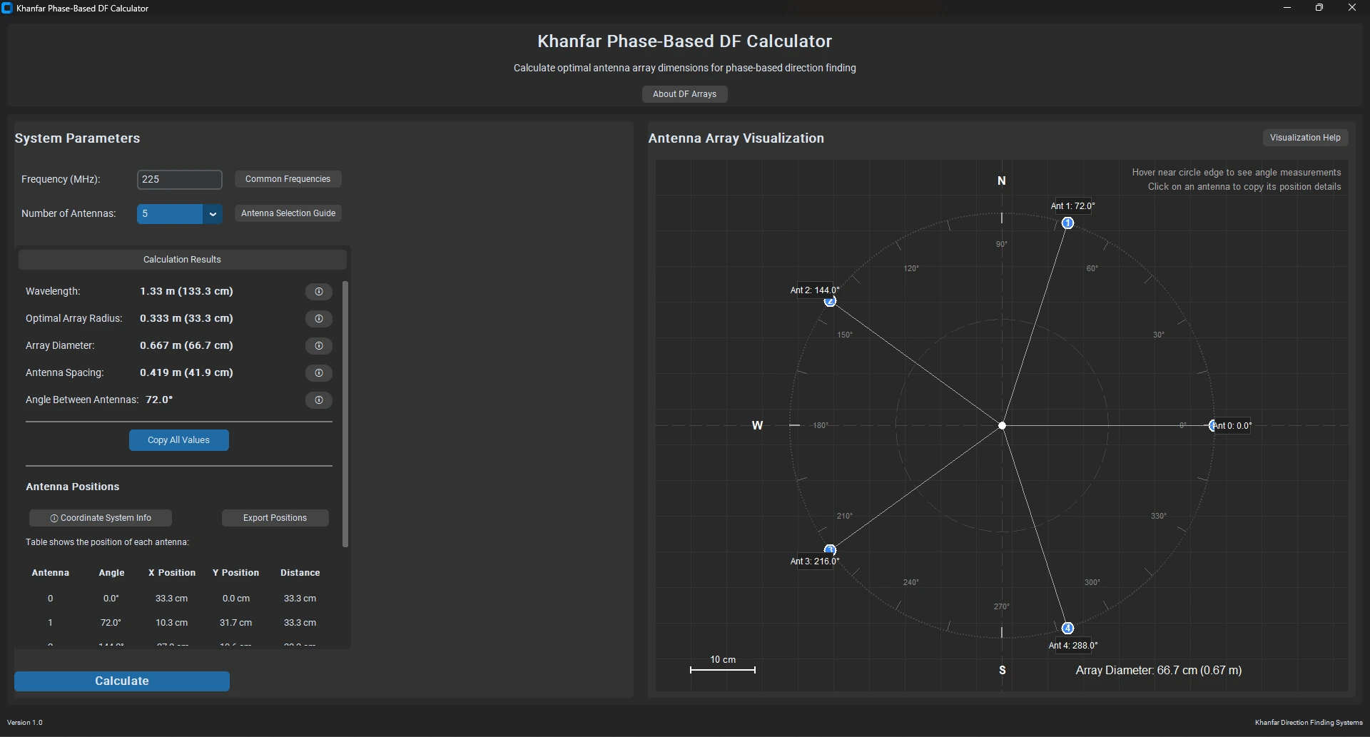
Khanfar Phase-Based Direction Finding Calculator
Specialized Tool for Designing Optimal Circular Antenna Arrays for Phase-Based Direction Finding Systems
The Khanfar Phase-Based Direction Finding (DF) Calculator is a specialized tool designed for radio engineers, amateur radio operators, and direction finding enthusiasts. This software helps you design optimal circular antenna arrays for phase-based direction finding systems by calculating precise antenna positions based on operating frequency and desired array configuration.
Key Features
Calculation Capabilities
- Optimal Sizing: Automatically calculates the ideal array radius (1/4 wavelength)
- Position Generation: Provides exact angles and coordinates for each antenna
- Spacing Verification: Ensures uniform antenna spacing around the array
- Wavelength Conversion: Handles all frequency-to-wavelength calculations
Visual Design Tools
- Interactive Array Visualization: Real-time display of antenna positions
- Coordinate System: Clear visual reference with cardinal directions
- Angular Measurement: Interactive angle indicator when hovering near the circle
- Click-to-Copy: Easy access to position details with one click
User Interface
- Modern Dark Interface: Reduced eye strain during extended use
- Comprehensive Tooltips: Context-sensitive help throughout the application
- Results Table: Detailed antenna position information
- Intuitive Controls: Simple parameter entry with real-time updates
Technical Specifications
Mathematical Approach
The calculator uses the following key formulas:
- Wavelength Calculation: λ = 300 / f (MHz)
- Optimal Array Radius: r = λ / 4
- Antenna Positions:
- Angle between antennas: θ = 360° / N (where N is the number of antennas)
- X position: X = r × cos(θ)
- Y position: Y = r × sin(θ)
Optimal Array Size
For phase-based DF, the ideal array radius is typically 1/4 wavelength, which provides:
- Maximum phase difference between antennas
- Reduced ambiguity in direction determination
- Optimal signal reception across the array
How to Use the Calculator
- Enter Parameters:
- Set the operating frequency in MHz (e.g., 433 MHz for UHF)
- Select the number of antennas in your array (3-8)
- Review Results:
- Check the calculated wavelength and array dimensions
- Review the antenna positions table with precise coordinates
- Utilize the Visualization:
- Examine the array configuration in the visual display
- Use the hover feature to measure angles precisely
- Click on antenna positions to copy coordinates to clipboard
- Implement in Hardware:
- Use the provided measurements to position antennas physically
- Enter the calculated radius into your DF processing software
System Requirements
- Operating System: Windows
- Resources: Minimal (suitable for most modern computers)
- Connectivity: No internet connection required (fully offline operation)
About Khanfar Direction Finding Systems
Khanfar Direction Finding Systems specializes in advanced radio direction finding technologies, providing tools and solutions for precise signal location and tracking. Our software is designed to bridge the gap between theoretical calculations and practical implementation in the field.
Unzip Password: 1234
Coming soon
This calculator is a complementary tool for the Khanfar Phase-Based Direction Finding system
Support Our Development
If you find our software useful and want to support our continued development, please consider making a donation. Your support helps us maintain and improve these tools for the entire RF community.
Please Donate
Help with the considerable costs:
• Hardware lots and lots of it
• Software
• And then there's the pet food! There's a new Kitty here, her name is Lulu and she likes food and balls!


Crypto Donation Address
Send your support to:
0x0c2b233268bdd2777afa57bc3ba350191dddbb12
Every contribution, no matter how small, helps us continue developing professional tools for the RF community.